


 Tiếng Việt
 한국어
한국어 中文 (中国)
 日本語
日本語What are shop drawings, and why are they essential in structural steel construction? Before steel components can be cut, drilled, welded, and erected, design information must be translated into precise fabrication instructions. Shop drawings perform this role by defining dimensions, materials, connections, welds, bolts, and identification marks for each component.
Drawing on nearly two decades of experience as an EPC contractor for structural steel projects, Nam Trung Construction understands how shop drawing quality directly affects fabrication accuracy, project coordination, construction progress, and on-site erection. In this article, we examine the roles, key information, responsible parties, and complete implementation process of structural steel shop drawings.
What Are Shop Drawings?
Shop drawings are detailed technical drawings prepared for the fabrication, assembly, and installation of specific construction components.
In structural steel projects, they translate the information contained in architectural drawings, structural drawings, specifications, connection requirements, and other contract documents into practical instructions that can be followed by the fabrication workshop and erection team.
The American Institute of Steel Construction’s Code of Standard Practice provides a common framework for defining responsibilities and accepted practices in structural steel contracting. AISC also publishes dedicated guidance addressing the preparation, review, and approval of structural steel shop detail drawings.
A typical structural drawing may show the location and design size of a beam, such as a particular rolled steel section. A shop drawing goes further by showing information such as:
- The exact length of the beam.
- End cuts and copes.
- Hole diameters and locations.
- Connection plates and stiffeners.
- Bolt quantities, sizes, and grades.
- Weld types, sizes, and locations.
- Material grade.
- Surface preparation and coating requirements.
- Member identification marks.
- Relevant tolerances and fabrication notes.
The objective is to provide enough verified information for the steel component to be produced accurately and assembled in the correct location.
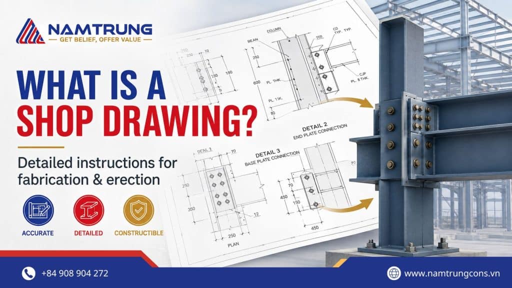
In steel construction, the terms shop drawing, detail drawing, and fabrication drawing are sometimes used interchangeably. Some companies make a distinction between approval drawings submitted for review and fabrication drawings formally released to production. The terminology and required drawing status should therefore be defined in the project specifications, contracts, or document-control procedures.
Why Are Shop Drawings Important in Steel Construction?
Structural steel components are commonly fabricated away from the construction site. Once fabrication begins, errors can result in material waste, workshop rework, delivery delays, installation problems, and costly site modifications.
Shop drawings create an opportunity to identify and resolve these issues before steel enters production.
Translating design intent into buildable information
Structural engineers focus on the safety, stability, strength, and serviceability of the structural system. Their drawings communicate design requirements but may not contain every production-level detail required by a specific fabricator.
Shop drawings translate that engineering information into component-level instructions that reflect practical fabrication and erection requirements.
Supporting accurate fabrication
Every plate, hole, cut, cope, weld, bolt, and connection must be located correctly. Shop drawings give workshop teams the dimensions and specifications needed to produce these items consistently.
When shop drawings are generated from a coordinated three-dimensional model, the same information can also support bills of materials, cutting lists, production schedules, and CNC fabrication data.
Modern steel-detailing platforms can generate fabrication-ready drawings, bills of materials, reports, and production data directly from an information-rich model while maintaining revision links between the model and its documentation.
Improving interdisciplinary coordination
Steel frames interact with architectural finishes, concrete structures, mechanical systems, equipment, façades, roofing, and other building components.
During shop drawing development, the project team can detect issues such as:
- Steel members conflicting with mechanical ducts.
- Anchor bolts not matching concrete foundations.
- Connection plates interfering with architectural finishes.
- Insufficient access for bolting or welding.
- Missing openings for equipment or piping.
- Inconsistent dimensions between architectural and structural drawings.
Resolving these issues before fabrication is generally more efficient than modifying completed steel components on site.
Supporting procurement and production planning
Shop drawing models and schedules provide detailed information about steel sections, plates, bolts, studs, coatings, and other materials. Fabricators can use this information to plan material purchasing, nesting, cutting, workshop capacity, fabrication sequences, delivery lots, and installation priorities.
Creating traceable project information
A controlled shop drawing process records technical comments, drawing revisions, approvals, deviations, and design clarifications. This creates a traceable information flow between the design team, contractor, detailer, fabricator, and erection team.
What Information Is Included in Structural Steel Shop Drawings?
The exact requirements depend on the project, contract, fabrication system, applicable standards, and client specifications. Nevertheless, a complete structural steel drawing package commonly contains the following information.
Project and document information
Each drawing should have a clear title block showing:
- Project name.
- Client or owner.
- Contractor or fabricator.
- Drawing title and number.
- Drawing scale.
- Preparation, checking, and approval details.
- Drawing status.
- Issue date.
- Revision number and revision description.
The latest approved revision must be clearly distinguishable from superseded versions.
Member identification
Every fabricated component is assigned a unique mark or position number.
The same identification is normally used across the three-dimensional model, shop drawing, material list, fabrication tracking system, delivery list, and erection drawing.
This allows the project team to follow each member from detailing through fabrication, coating, packing, delivery, and installation.
Geometry and dimensions
Drawings should provide the dimensions required to fabricate the component without relying on assumptions.
These may include:
- Overall member length.
- Plate width, length, and thickness.
- Hole diameter and spacing.
- Cut angles.
- Cope dimensions.
- Camber requirements.
- Stiffener locations.
- Edge distances.
- Connection offsets.
- Weld preparation dimensions.
Dimensions should be coordinated and presented in a way that minimizes the risk of misinterpretation.
Materials and steel grades
Shop drawings usually identify the steel section, plate thickness, material grade, and applicable material specifications. Where required, the documentation may also provide traceability information connected with mill certificates, heat numbers, or material identification procedures.
Bolted connections
For bolted connections, the drawings may show:
- Bolt diameter.
- Bolt grade.
- Number of bolts.
- Hole type.
- Bolt spacing.
- Edge distances.
- Washer requirements.
- Installation notes.
- Connection orientation.
The required level of information depends partly on whether the connection has been fully designed by the engineer of record or delegated to another qualified party.
Welded connections
Weld information may include:
- Weld type.
- Weld size.
- Weld length.
- Weld location.
- Shop or field weld identification.
- Weld preparation.
- Welding symbols.
- Special inspection or testing requirements.
The drawing should be read together with the project welding specifications and approved welding procedures.
Surface treatment and coating
Shop drawings and associated schedules may identify:
- Surface preparation requirements.
- Primer or coating system.
- Galvanizing requirements.
- Fire-protection interface conditions.
- Areas that must remain unpainted.
- Touch-up requirements.
- Architecturally exposed structural steel requirements.
Architecturally exposed structural steel requires particularly clear coordination because appearance expectations can influence fabrication, welding, grinding, handling, coating, transport, and erection. AISC emphasizes coordination among owners, architects, engineers, contractors, fabricators, detailers, and erectors when AESS is specified.
Bill of materials
A bill of materials, or BOM, may be included on individual drawings or issued as a separate report.
It can contain:
- Part marks.
- Quantities.
- Steel profiles.
- Plate sizes.
- Material grades.
- Unit weights.
- Total weights.
- Surface areas.
- Remarks.
The BOM supports purchasing, inventory management, production planning, costing, packing, and delivery control.
Main Types of Steel Shop Drawings
A structural steel detailing package usually contains several related types of drawings and reports.
Single-part drawings
Single-part drawings describe individual components before they are assembled with other parts.
Examples include:
- Plates.
- Angles.
- Cleats.
- Stiffeners.
- Brackets.
- Individual beams or columns.
- Connection components.
The drawings show the exact geometry, holes, cuts, dimensions, and material specifications required for production.
Assembly drawings
Assembly drawings show how multiple parts are welded or bolted together to create a fabricated assembly.
A beam assembly drawing, for example, may show the main beam together with end plates, stiffeners, cleats, shear tabs, and other attached parts.
Assembly drawings usually contain member marks, dimensions, weld information, orientation details, and a list of the parts included in the assembly.
Tekla Structures classifies fabrication documentation into formats such as single-part drawings and assembly drawings, which can be produced based on selected model objects and controlled drawing settings.
General arrangement drawings
General arrangement drawings show the overall relationship between structural steel components.
They may present:
- Building grids.
- Floor levels.
- Column locations.
- Beam layouts.
- Bracing systems.
- Truss arrangements.
- Major dimensions.
- Interface locations.
These drawings assist coordination but do not normally replace the detailed information provided on individual shop drawings.
Erection drawings
Erection drawings show where each fabricated assembly is installed on site.
They typically include:
- Grid references.
- Elevations.
- Member marks.
- Assembly orientations.
- Field connections.
- Field bolts and welds.
- Erection sequence references.
- Temporary conditions where specified.
- Interface details.
Shop drawings primarily guide fabrication, while erection drawings guide the positioning and connection of components at the construction site.
Anchor bolt and embedded-item drawings
These drawings provide the dimensions and setting-out information required to install anchor bolts, embed plates, sleeves, and other items before the steel frame arrives.
Because these items interact directly with concrete work, early coordination is essential.
An anchor bolt error can prevent a column base plate from fitting correctly and may require engineering review, foundation modification, or steel rework.
Specialized steel drawings
Depending on the project scope, separate drawing packages may be prepared for:
- Steel stairs.
- Handrails.
- Ladders.
- Platforms.
- Gratings.
- Canopies.
- Equipment supports.
- Pipe racks.
- Crane structures.
- Steel façades.
- Architecturally exposed steel.
Shop Drawings vs. Construction Drawings
Construction drawings and shop drawings serve different purposes.
Construction drawings are normally prepared by architects and design engineers. They communicate the overall design, performance requirements, dimensions, structural system, and project specifications.
Shop drawings are typically prepared under the responsibility of a contractor, fabricator, supplier, specialist subcontractor, or appointed detailer. They show how a specific component will be manufactured and installed.
The main differences can be summarized as follows:
Construction drawings:
- Communicate the overall design intent.
- Cover the complete building or structural system.
- Are prepared by the design team.
- Form part of the contract documentation.
- Define the required design and performance criteria.
Shop drawings:
- Focus on specific fabricated components.
- Contain production-level information.
- Are normally prepared by a fabricator, supplier, contractor, or detailer.
- Are submitted for coordination and review.
- Guide fabrication, assembly, and installation.
Architectural and engineering documents are not generally intended to serve as a complete instruction manual for the contractor’s construction methods. The contractor’s work planning, schedules, submittals, and shop drawings establish how the work will be executed within the requirements of the contract documents.
Shop drawings also differ from as-built drawings. Shop drawings are produced before fabrication and installation, whereas as-built documents record the final installed conditions, including approved changes made during construction.
Who Prepares and Reviews Shop Drawings?
Shop drawing development is a collaborative process. The exact responsibilities must be established in the contract, specifications, responsibility matrix, and project execution plan.
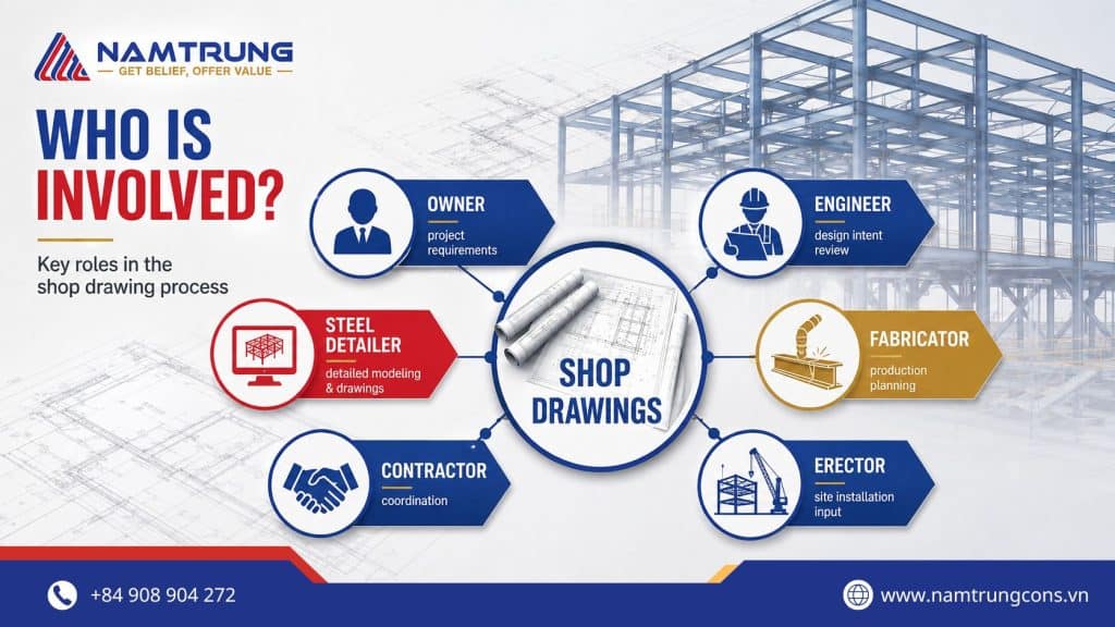
Owner or project developer
The owner defines the project requirements, performance expectations, schedule, and contractual framework.
The owner may also establish document-submission procedures, approval authorities, and digital delivery requirements.
Architect
The architect reviews matters related to architectural intent, dimensions, appearance, interfaces, finishes, and coordination with the overall building design.
For exposed steel, the architect may define visual requirements, acceptable finish quality, and areas requiring special treatment.
Structural engineer of record
The structural engineer establishes the structural design requirements and reviews shop drawing submissions for general conformance with the structural design information and design concept expressed in the contract documents.
The engineer’s review does not normally transfer responsibility for fabrication dimensions, quantities, field measurements, construction means, or contractor coordination. The precise legal effect of a review stamp depends on the contract and applicable jurisdiction.
AIA guidance describes the architect’s review of shop drawings and similar submittals as a limited review for conformance with the information and design concept contained in the contract documents.
General contractor or EPC contractor
The main contractor coordinates the shop drawing schedule with procurement, civil works, architectural works, MEP systems, fabrication, delivery, and construction activities.
Before forwarding a submittal to the design team, the contractor may be required to confirm that it has been coordinated with field conditions and other trades.
Steel fabricator
The fabricator is responsible for producing the steel components according to the approved information and applicable fabrication procedures.
The fabricator usually provides input on:
- Available materials.
- Workshop equipment.
- Preferred connection details.
- Welding and cutting capabilities.
- Transport limitations.
- Assembly strategy.
- Production sequencing.
- Quality-control requirements.
Steel detailer
The steel detailer develops the detailed model, shop drawings, erection drawings, bills of materials, and related fabrication data.
The detailer must interpret the design documents, identify missing information, coordinate interfaces, prepare RFIs, manage drawing revisions, and ensure consistency between drawings and the model.
The detailer should not independently change the structural design. Unclear or conflicting requirements must be submitted to the authorized designer for clarification.
Connection design engineer
On some projects, the engineer of record fully designs and documents the steel connections.
On other projects, connection design may be delegated to a qualified engineer working for the contractor or fabricator. The project documents should clearly define the connection-design criteria, design loads, required calculations, submission procedure, and professional responsibility.
Steel erector
The erector reviews erection drawings and may provide input regarding:
- Installation sequence.
- Site access.
- Crane positioning.
- Lifting limitations.
- Temporary stability.
- Field connection access.
- Assembly size.
- Delivery sequence.
Early erector involvement can help ensure that detailed steel components are not only fabricable but also practical to transport and install.
Structural Steel Shop Drawing Implementation Process
A reliable shop drawing workflow should be planned before detailing begins. The following process represents a typical structural steel project.
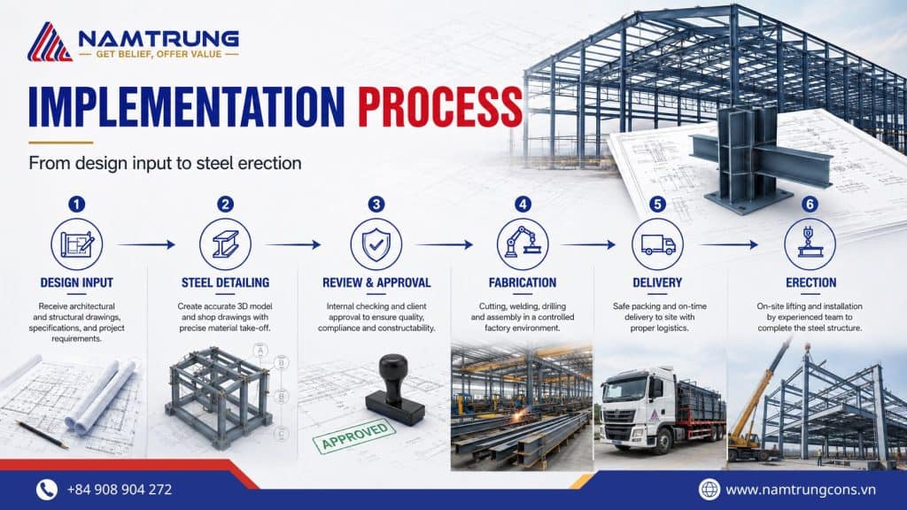
Step 1: Receive and review project inputs
The detailer and fabricator receive the available project documents, which may include:
- Architectural drawings.
- Structural drawings.
- Specifications.
- Design calculations.
- Connection details.
- BIM models.
- Equipment drawings.
- MEP layouts.
- Project standards.
- Client drafting requirements.
- Fabrication and coating specifications.
The team checks whether the information is complete, consistent, and suitable for detailing.
Step 2: Confirm scope and responsibilities
A detailing kick-off meeting should establish:
- The steel scope.
- Drawing package breakdown.
- Connection-design responsibility.
- Required software and file formats.
- Model coordinates and grid systems.
- Approval workflow.
- Drawing status codes.
- Review periods.
- Priority zones.
- Fabrication sequences.
- Required reports and CNC data.
This prevents uncertainty about who is responsible for each technical decision.
Step 3: Identify missing or conflicting information
The detailer compares architectural, structural, civil, and equipment information.
Questions or discrepancies are recorded and submitted through requests for information, or RFIs.
Typical RFIs relate to:
- Missing connection loads.
- Conflicting grid dimensions.
- Undefined steel elevations.
- Inconsistent member sizes.
- Missing equipment loads.
- Unclear coating requirements.
- Concrete dimensions that do not match steel setting-out information.
RFIs should be submitted early because unresolved questions can delay the entire drawing package. AISC training materials identify timely responses to RFIs as an important factor in maintaining approval-drawing schedules.
Step 4: Develop the steel detailing model
The detailer creates a coordinated model containing structural members, plates, bolts, welds, holes, cuts, and connections.
The model should follow the project coordinate system, steel elevations, member orientations, material specifications, and approved design requirements.
Where a federated BIM process is used, the steel model may be coordinated with architectural, concrete, MEP, equipment, and façade models.
Step 5: Detail connections and interfaces
Connections are developed according to the project’s defined design responsibilities.
The detailer also coordinates:
- Column bases and anchor bolts.
- Steel-to-concrete interfaces.
- Equipment supports.
- Roof and cladding interfaces.
- Openings and penetrations.
- Stairs and platforms.
- Mechanical and electrical clearances.
- Field splice locations.
- Transportation and lifting restrictions.
Any proposed deviation from the design documents must be clearly identified and approved by the authorized party.
Step 6: Perform constructability and clash checks
Before producing drawings, the model should be checked for physical conflicts and practical construction issues.
The team should verify:
- Bolt and welding access.
- Member clearances.
- Connection fit.
- Erection access.
- Lifting feasibility.
- Transport dimensions.
- Drainage and coating access.
- Assembly weight.
- Interface dimensions.
- Temporary stability considerations.
This stage helps prevent components from being technically correct on paper but difficult to fabricate or erect.
Step 7: Generate shop drawings and reports
After model coordination, the detailer produces:
- Single-part drawings.
- Assembly drawings.
- Erection drawings.
- General arrangement drawings.
- Anchor bolt drawings.
- Material lists.
- Bolt lists.
- Drawing registers.
- CNC or machine data where required.
Automated drawing generation can improve productivity, but each output must still be reviewed. Automation does not remove the need for technical checking and professional judgment.
Step 8: Conduct internal checking
Before submission, a checker who was not solely responsible for the original detailing should review the model and drawings.
The checker verifies:
- Member sizes and materials.
- Dimensions.
- Connection geometry.
- Bolt and weld information.
- Drawing clarity.
- Part and assembly marks.
- Revision status.
- Interfaces.
- BOM consistency.
- Compliance with project requirements.
Fabricators operating under a documented quality management system are better positioned to maintain consistent procedures, inspection records, and traceable quality controls throughout fabrication.
Step 9: Submit approval documents
The checked drawings are transmitted through the agreed document-control system.
The submission should identify:
- Drawing numbers.
- Revision numbers.
- Drawing status.
- Submission purpose.
- Required response date.
- Related RFIs.
- Deviations or assumptions.
- Areas requiring specific review.
Large projects should divide submissions into logical fabrication or construction packages rather than sending an unmanageable number of drawings at once.
Step 10: Review and respond to comments
The contractor, architect, structural engineer, and other responsible parties review the submission within their defined scope.
Common response statuses include:
- Approved.
- Approved as noted.
- Revise and resubmit.
- Rejected.
- For information only.
Terminology varies between projects, so the meaning of each status must be defined.
Comments should be specific, coordinated, and traceable. Contradictory comments from different reviewers should be resolved before drawings are revised.
Step 11: Revise and release for fabrication
The detailer incorporates authorized comments and issues a new revision.
All changes should be clearly identified, and previous versions should be removed from active production systems.
Only drawings with the required release status should be used for purchasing, cutting, drilling, welding, assembly, coating, or delivery.
Revision control is critical. Fabricating from a superseded drawing can produce components that no longer match the approved design or current site conditions.
Step 12: Support fabrication and erection
Questions may still arise during production or installation.
The detailer, fabricator, contractor, and engineer must maintain a controlled process for:
- Workshop queries.
- Nonconformance reports.
- Field modifications.
- Design changes.
- Replacement members.
- Revised connection details.
- Site-measurement updates.
Approved changes must be reflected consistently across the model, shop drawings, erection drawings, reports, and production data.
Common Shop Drawing Errors
Many shop drawing problems originate from incomplete coordination rather than drafting alone.
Common errors include:
- Using outdated design drawings.
- Missing revision information.
- Incorrect member orientation.
- Inconsistent dimensions.
- Incorrect material grades.
- Unresolved architectural and structural conflicts.
- Missing weld or bolt information.
- Anchor bolt misalignment.
- Insufficient access for installation.
- Unapproved design changes.
- Inconsistent member marks.
- BOM quantities that do not match drawings.
- Releasing drawings before RFIs are resolved.
- Failing to update erection drawings after revisions.
These issues can be reduced through disciplined input control, model coordination, independent checking, clear approval procedures, and strict revision management.
Shop Drawing Quality Checklist
Before releasing structural steel shop drawings, the project team should confirm that:
- The latest architectural and structural documents have been used.
- All relevant RFIs have been answered.
- Drawing numbers, revisions, dates, and statuses are correct.
- Every member and part has a unique identification mark.
- Member sizes and material grades match the design requirements.
- Dimensions are complete and consistent.
- Holes, cuts, copes, plates, and stiffeners are fully defined.
- Bolt information is complete.
- Weld symbols and requirements are clear.
- Shop welds and field welds are correctly identified.
- Coating and surface-treatment requirements are included.
- Concrete, equipment, façade, and MEP interfaces have been checked.
- Fabrication and erection access has been considered.
- Bills of materials match the drawings and model.
- Drawing comments from previous reviews have been closed.
- Superseded files have been removed from active use.
- Erection drawings reflect the latest fabrication information.
- The drawing package has completed internal checking.
The Role of BIM in Shop Drawing Production
Traditional shop drawings can be prepared using two-dimensional CAD. However, three-dimensional steel detailing has become increasingly valuable for complex industrial buildings, factories, plants, warehouses, pipe racks, and export steel structures.
A model-based workflow allows the team to coordinate geometry before drawings are released. It can also connect drawing production with material reports, revision management, CNC data, fabrication planning, and project collaboration.
Tekla’s steel-detailing workflow, for example, supports constructible modeling, fabrication-ready drawings, BOM generation, reports, automated revision management, and interfaces with production systems and CNC machinery.
Nevertheless, software is only a tool. The quality of the final output still depends on:
- Accurate design inputs.
- Experienced detailers.
- Clear contractual responsibilities.
- Proper engineering decisions.
- Independent checking.
- Effective communication.
- Controlled revisions.
A highly detailed model based on incorrect or incomplete information can still produce incorrect fabrication drawings.
How to Select a Steel Shop Drawing and Fabrication Partner
A suitable detailing and fabrication partner should demonstrate more than drafting capacity.
Project owners and contractors should evaluate whether the supplier has:
- Experience with comparable steel structures.
- In-house engineering and detailing coordination.
- Competent checkers and quality-control personnel.
- Suitable BIM and steel-detailing software.
- Documented drawing and revision procedures.
- Connection-design coordination capability.
- Integration between detailing and fabrication.
- Material traceability systems.
- Suitable workshop machinery.
- Welding and inspection procedures.
- Export packing and logistics experience where applicable.
- The ability to provide fabrication and erection support.
The strongest workflow is normally achieved when design coordination, shop detailing, fabrication planning, quality control, and production teams work through a common information system.
Structural Steel Shop Drawings at Nam Trung Construction
At Nam Trung Construction, shop drawing development is integrated with structural steel fabrication and project execution.
Our team coordinates design information, develops detailed steel models, prepares fabrication and erection drawings, and connects drawing data with material planning and workshop production.
This integrated approach supports:
- Early identification of design and interface conflicts.
- Practical connection and fabrication planning.
- Accurate bills of materials.
- Controlled drawing revisions.
- Efficient steel cutting and assembly.
- Trial assembly where required.
- Export packing and logistics coordination.
- Technical support during erection.
By combining engineering coordination, steel detailing, fabrication, quality control, and delivery planning, Nam Trung helps clients reduce information gaps between design offices, fabrication workshops, and construction sites.
Frequently Asked Questions About Shop Drawings
Who prepares structural steel shop drawings?
Shop drawings are commonly prepared by a steel detailer working for or appointed by the steel fabricator, specialist subcontractor, general contractor, or EPC contractor. The contractual arrangement determines the responsible party.
Are shop drawings prepared by the structural engineer?
The structural engineer normally prepares the structural design documents. The engineer may also prepare specific details or connection designs, but production-level shop drawings are typically prepared under the fabricator’s or contractor’s responsibility.
Are shop drawings the same as fabrication drawings?
The terms are often used interchangeably. Some projects distinguish between drawings submitted for approval and drawings officially released for workshop production. The project document-control procedure should define the terminology.
Can fabrication begin before shop drawings are approved?
Fabrication should only begin when drawings have received the release status required by the contract and quality procedures. Starting production too early creates a risk of rework if the design or drawing is later revised.
Does engineer approval make the engineer responsible for shop drawing errors?
Not necessarily. Reviews are generally limited to the reviewer’s defined contractual scope. Fabricators and contractors commonly retain responsibility for dimensions, quantities, coordination, fabrication methods, and field conditions. The governing contract and local law should always be checked.
What software is used to produce steel shop drawings?
Common tools include structural BIM, steel-detailing, and CAD platforms. The appropriate system depends on project size, complexity, client requirements, fabrication equipment, and required data formats. Tekla Structures is one widely used example for model-based steel detailing and fabrication documentation.
Conclusion
Shop drawings are the practical link between structural design and physical construction.
They convert design requirements into the detailed information needed to procure materials, manufacture individual steel parts, assemble components, control quality, plan deliveries, and erect the structure safely and accurately.
Their value does not come from drawing detail alone. An effective shop drawing process requires clear responsibilities, complete design inputs, early RFIs, coordinated modeling, constructability reviews, independent checking, controlled approvals, and disciplined revision management.
For industrial steel buildings and complex structural steel projects, integrating shop drawing development with fabrication and erection planning can significantly improve coordination and reduce avoidable workshop and site problems.
NAM TRUNG DESIGN & CONSTRUCTION CONSULTING JOINT STOCK COMPANY
A leading EPC contractor for civil, industrial, commercial, and infrastructure projects in Southeast Vietnam.
 119 Le Loi Street, Phu My Ward, Ho Chi Minh City, Vietnam
☎ (+84) 908 90 42 72 / (+84) 908 42 42 72
✉ sales@namtrungcons.com namtrungcons.vn | namtrungcons.com
